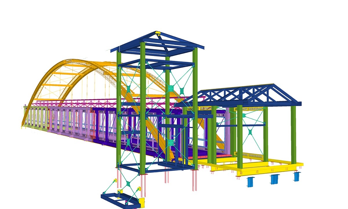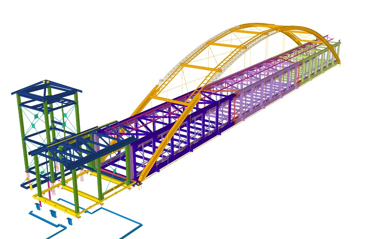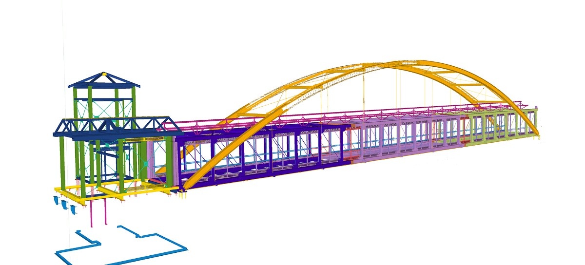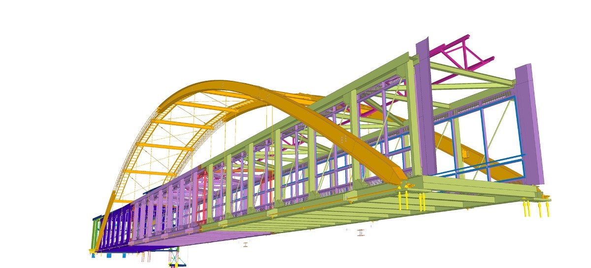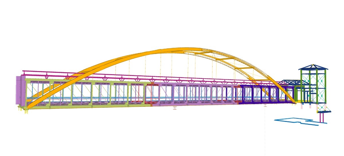
Cambered replacement girders
The 6.2-ton emergency repair package included beam girders modeled against the existing bridge geometry.
Infrastructure & Transportation
Emergency bridge repair detailing where every component mattered.
Project overview
The project involved emergency repairs to MnDOT Pedestrian Bridge No. 62023 over Trunk Highway 52 in the Cesar Chavez Street and Concord Street area of Saint Paul, Minnesota.
The scope included the replacement and repair of critical structural steel components.
Working for Zimmerman Metals, our team modeled and detailed approximately 6.2 tons of repair steel using Tekla Structures.
Detailing scope
The 6.2-ton emergency repair package included beam girders modeled against the existing bridge geometry.
Secondary components were located relative to the cambered girders and coordinated repair structure.
Splices were detailed for field assembly as part of the replacement and repair scope.
Bearing-related plate positions and welded stud locations were represented precisely in the fabrication information.
A Tekla model and fabrication drawings were developed for Zimmerman Metals in approximately 160 detailing hours.
Technical complexity
New components had to align with established bridge elevations and girder camber rather than an entirely new structural layout.
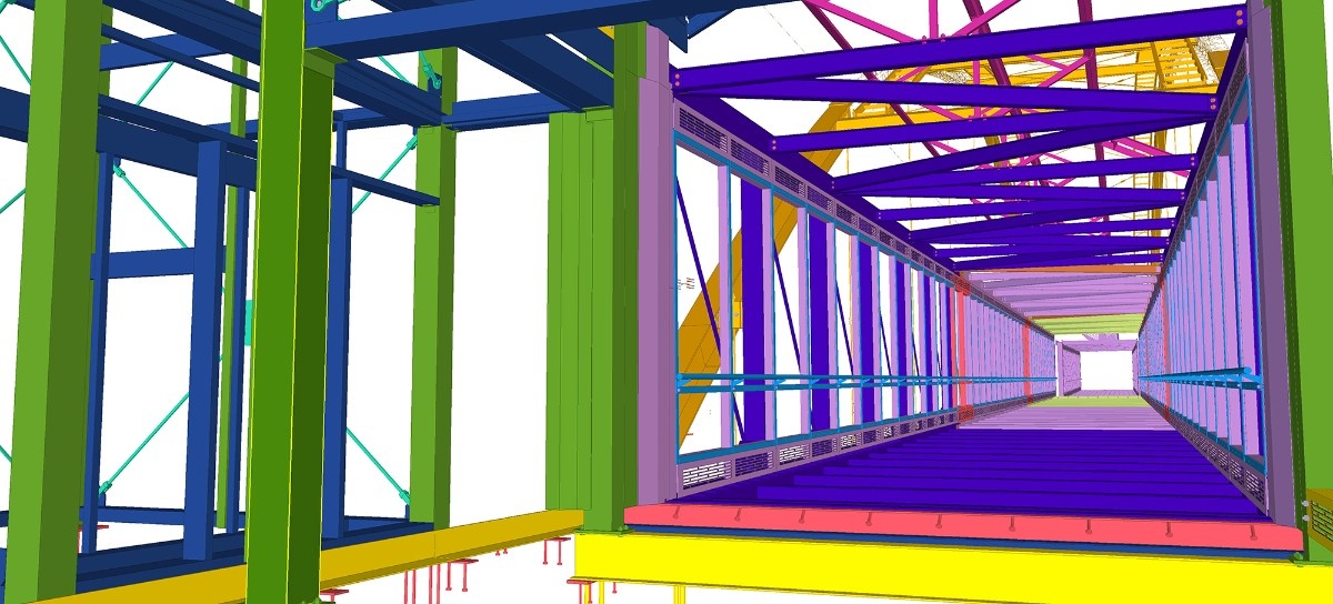
Diaphragms, bracing, sole plates and shear studs required accurate placement relative to the cambered girders.
Fabricated components and field-assembled splice connections had to be communicated clearly within one coordinated emergency repair package.
Our approach
The entire repair structure was modeled in Tekla Structures.
The model provided a consistent basis for:
Our team dedicated approximately 160 hours to the modeling and detailing scope.
Project result
The completed scope included a coordinated Tekla model and fabrication documentation for approximately 6.2 tons of replacement and repair steel.
Despite its relatively low tonnage, the project required detailed attention to the interfaces between new components and the existing pedestrian bridge.