Structural and miscellaneous steel
Comprehensive detailing for approximately 1,400 tons of primary framing, secondary steel and miscellaneous components in accordance with the AISC Code of Standard Practice.
Commercial · Bozeman, Montana, USA
Design detailing for 1,400 tons of structural steel shaped by complex geometry.
Project overview
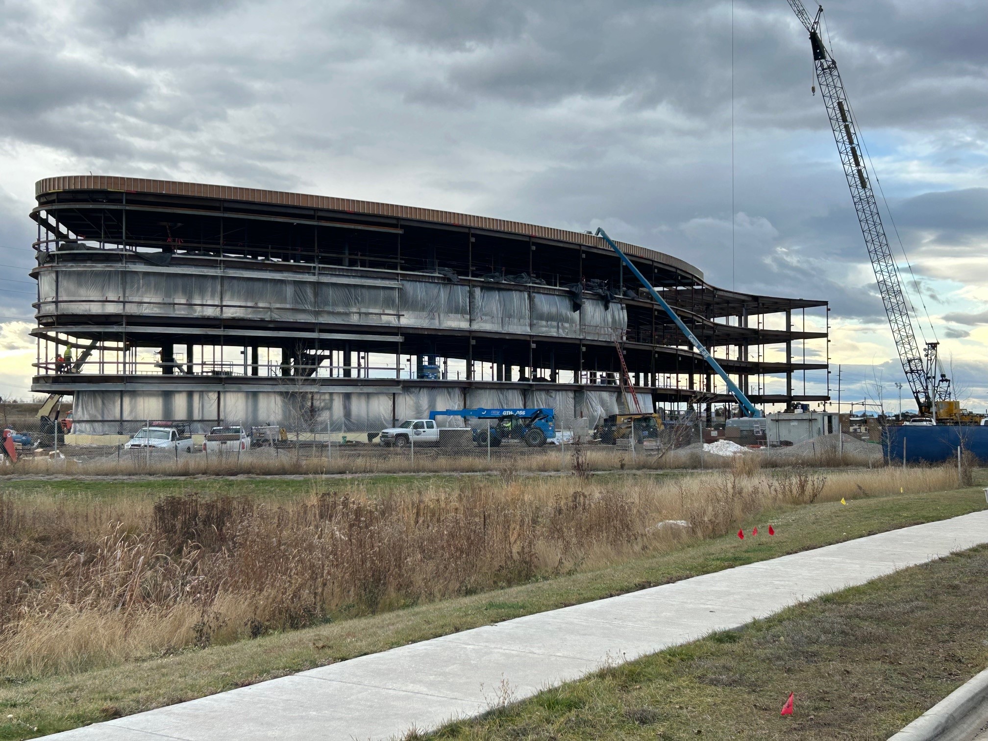
The Barnard Office Complex in Bozeman, Montana, serves as the corporate headquarters of Barnard Construction, a heavy civil contractor delivering major infrastructure projects across North America.
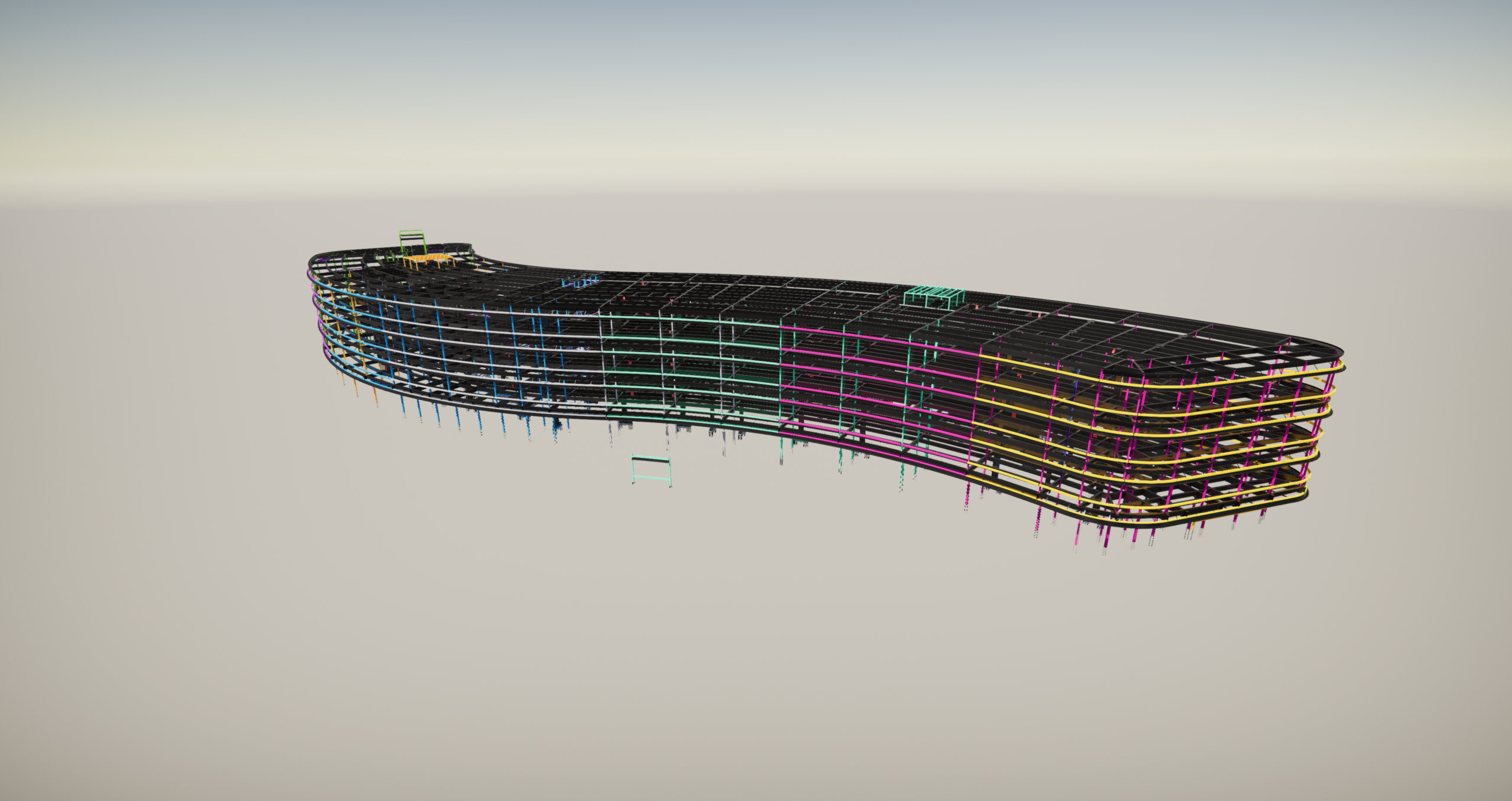
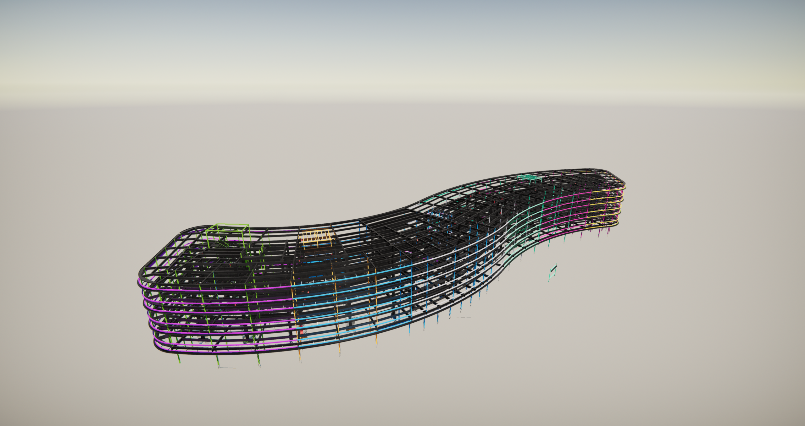
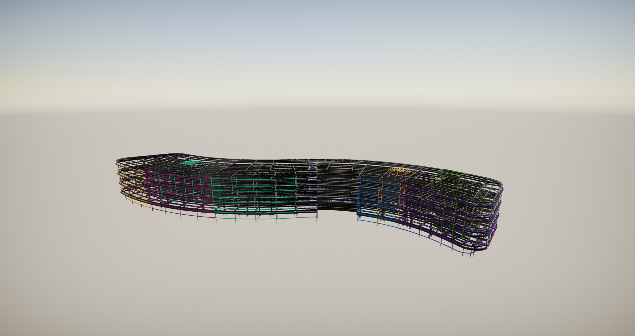
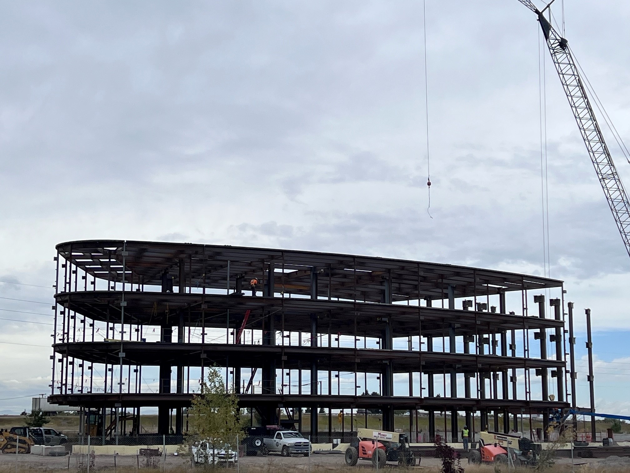
The approximately 1,400-ton structure is defined by its distinctive S-shaped form. This geometry created continuously changing framing relationships, non-standard member alignments and numerous project-specific connection conditions.
Working with TrueNorth Steel, our team delivered the project as a Design Detailing assignment, developing the steel model and fabrication information in parallel with the ongoing structural design.
Unlike a conventional detailing process based on a substantially complete design package, this project required the Tekla model to develop alongside the design itself.
New and revised information had to be incorporated continuously while maintaining coordination between structural intent, connection requirements and fabrication needs. Close communication with the fabricator and design team allowed the model to remain aligned with the developing structure throughout the project.
Detailing scope
Comprehensive detailing for approximately 1,400 tons of primary framing, secondary steel and miscellaneous components in accordance with the AISC Code of Standard Practice.
The SidePlate™ system was modeled and documented with its beams, columns, connection components and adjacent framing.
Member orientations, framing angles and connections were developed for the building’s continuously varying curved plan.
The Tekla model supported drawings and fabrication data for wide-flange members, HSS, pipe, tees, angles, channels and plate components.
Model to field
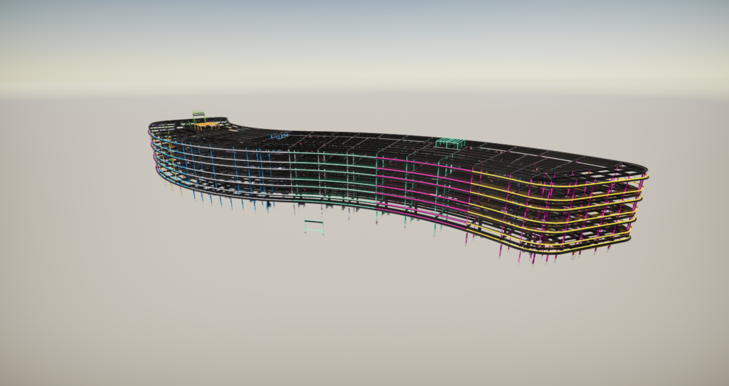 01 / Coordinated model
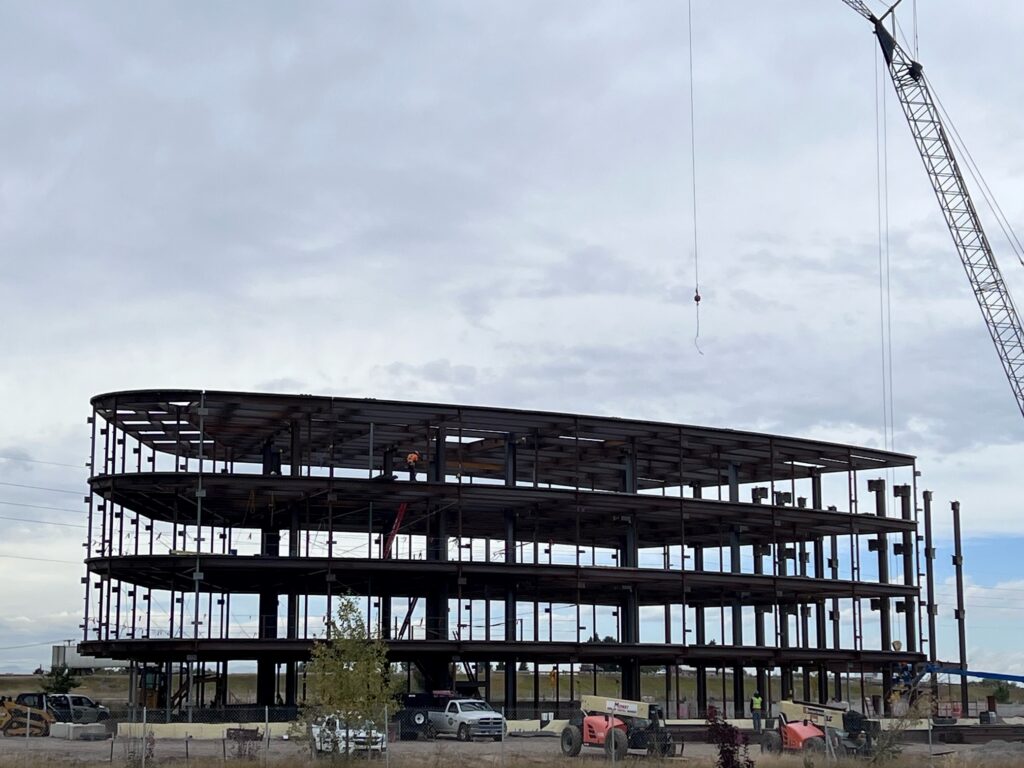 02 / Fabrication & field
Technical complexity
The model developed alongside the structural design. New information had to be incorporated while maintaining alignment with connection and fabrication requirements.
The S-shaped plan produced changing member orientations and framing angles, limiting the use of standard repetitive connection details.
SidePlate™ components had to remain coordinated with the surrounding framing at individual locations throughout the developing structure.
Our approach
The Design Detailing process required continuous coordination between Anatomic, TrueNorth Steel and the design team.
Our approach focused on:
This collaborative workflow supported the transition of a complex architectural and structural concept into a coordinated steel package ready for fabrication.
A key feature of the structural system was the use of SidePlate™ moment connections. These connections had to be accurately incorporated into the overall framing system and coordinated with the building’s changing geometry.
Our detailing scope included modeling and documenting the SidePlate™ system in accordance with the project requirements, while maintaining the required relationships between beams, columns, connection components and adjacent framing.
Because the building geometry created many non-repetitive conditions, the integration of these moment connections required close attention to individual locations throughout the structure.
The building’s curved plan generated structural conditions that varied continuously along its length. Member orientations, framing angles and connection geometry changed throughout the structure, limiting the use of standard repetitive details.
The model included a wide range of steel components and profiles:
Each condition had to be clearly represented in the model and drawings while accounting for fabrication requirements and erection fit-up.
Project result
Our scope covered comprehensive structural and miscellaneous steel detailing in accordance with the AISC Code of Standard Practice.
The Tekla model was used to coordinate primary and secondary structural steel, connection systems and miscellaneous components as design information continued to develop. Potential conflicts and difficult framing conditions could therefore be identified and addressed before the affected steel reached fabrication.
The resulting model supported the production of shop drawings, erection drawings and fabrication data for the wide range of members and connection conditions included in the project.