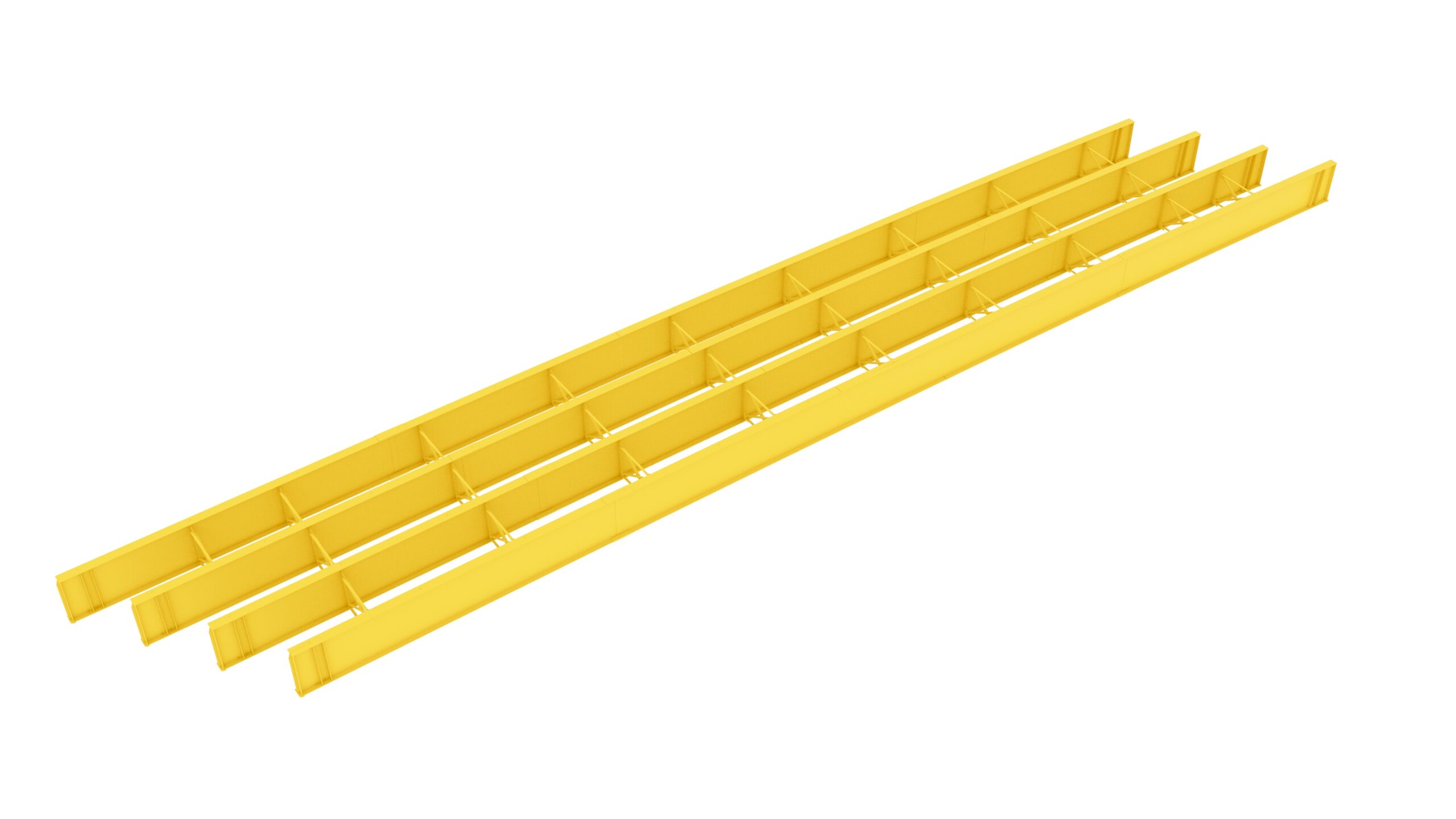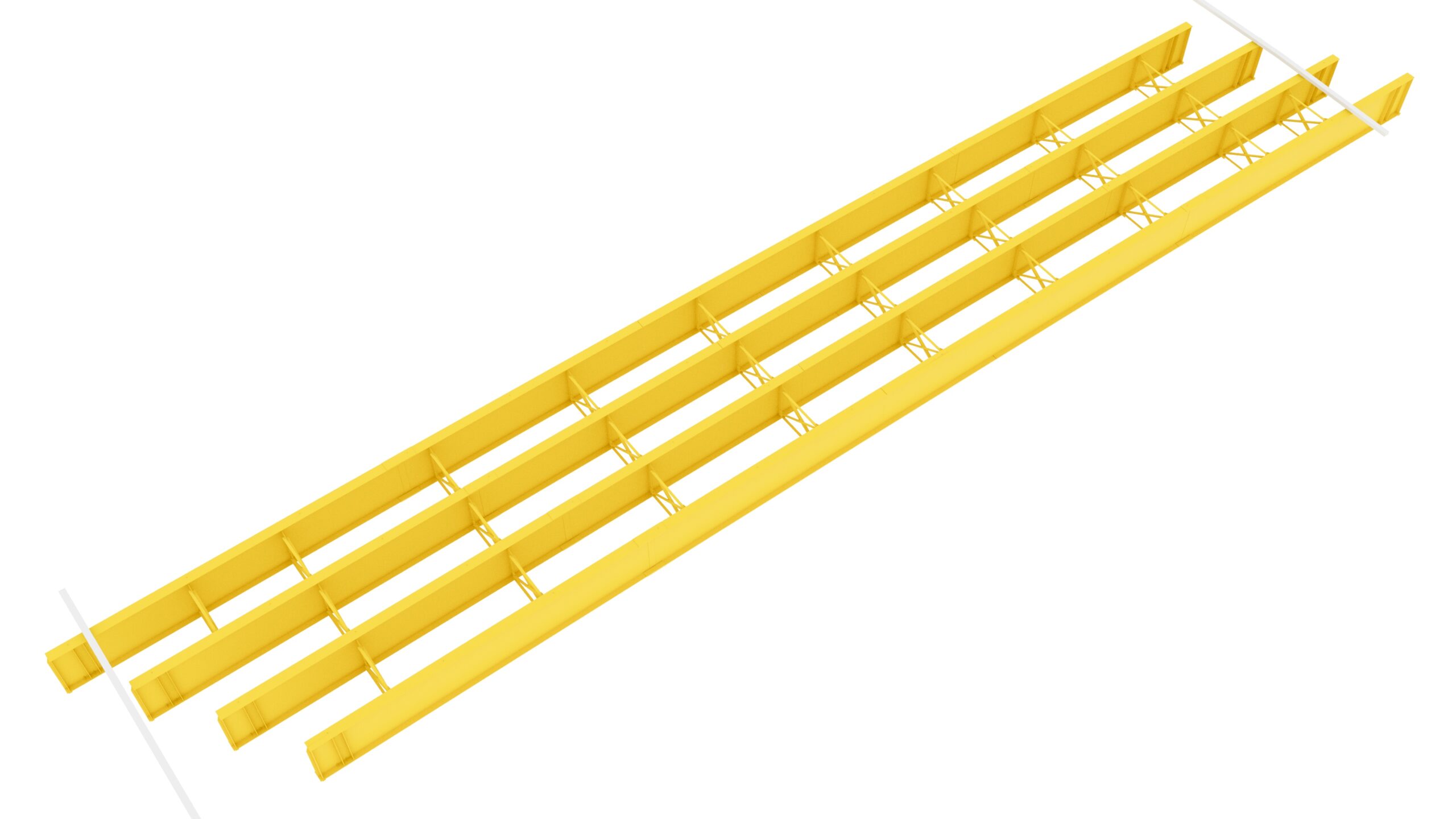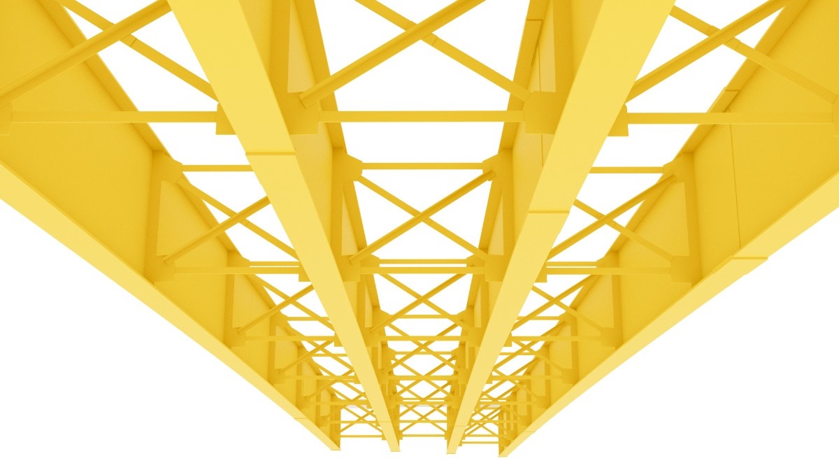
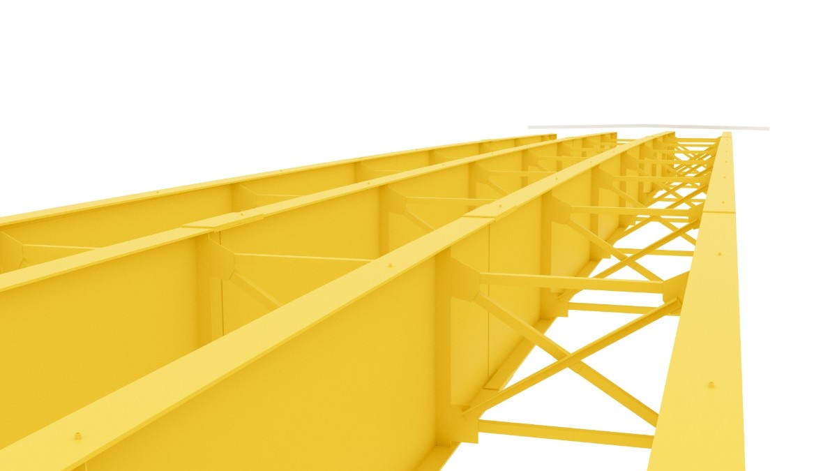
Plate girder bridge geometry
The complete 250-ton, 224-foot bridge was modeled in Tekla Structures for TrueNorth Steel.
Infrastructure & Transportation
Bridge detailing driven by elevation, camber and connection accuracy.
Project overview
The 2nd Avenue Grant County Bridge is located between Tioga Street and Walnut Street in Big Stone City, South Dakota.
The steel plate girder bridge has an overall length of 224 feet and incorporates approximately 250 tons of structural steel. TrueNorth Steel delivered the bridge in cooperation with SDDOT, BNSF and R.R. Schroeder Construction.
Our team fully modeled and detailed the structure using Tekla Structures.
Detailing scope
The complete 250-ton, 224-foot bridge was modeled in Tekla Structures for TrueNorth Steel.
Girder positions and the bridge profile were developed with elevations and camber controlled along the full structure.
Connection conditions were modeled and represented in fabrication drawings against the coordinated bridge geometry.
Drawing content and presentation were adapted to TrueNorth Steel’s specialized requirements during approximately 400 detailing hours.
Technical complexity
The bridge could not be represented as uniform horizontal building levels. Its elevation layout had to maintain the designed girder profile throughout.
Welded and bolted conditions needed detailed drawings that preserved the relationship between connection requirements and modeled geometry.
Specialized drawing requirements had to be incorporated while retaining consistency with the complete Tekla bridge model.
Our approach
TrueNorth Steel had specialized requirements for the project drawings.
Using Tekla Structures, our team adjusted the drawing content and presentation to match those requirements while maintaining consistency with the coordinated bridge model.
Approximately 400 hours were dedicated to modeling and detailing the complete steel package.
The entire bridge structure was developed as a detailed Tekla model.
Tekla Structures enabled the team to define the bridge geometry, members and connection conditions while also adapting the drawing output to TrueNorth Steel’s specific requirements.
The model served as the basis for the project’s fabrication and erection documentation.
The bridge incorporated a variety of welded and bolted connections.
Each condition required clear and detailed representation in the drawings so that the fabrication information reflected the modeled geometry and connection requirements.
The detailing scope included:
Project result
The completed scope included the Tekla model together with fabrication and erection documentation for approximately 250 tons of structural steel.
The project combined bridge-specific geometry, camber control, multiple connection types and customized drawing requirements within one coordinated detailing process.