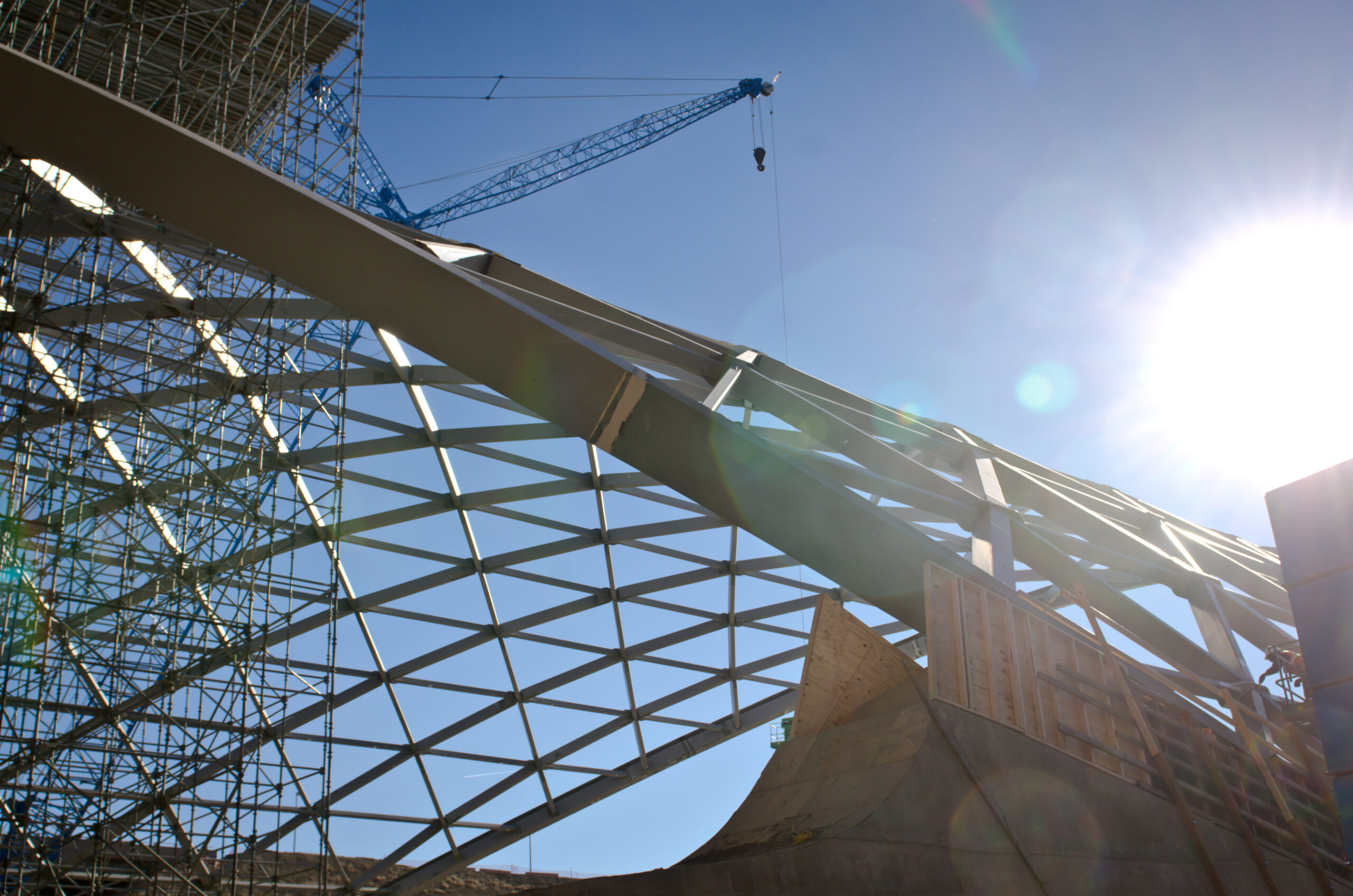
Hotel and transit-center steel
More than 2,300 tons of structural steel were developed through the collaborative design-detailing process.
Design Detailing · Denver, Colorado
Complex steel detailing for a landmark hotel and transit center.
Project overview
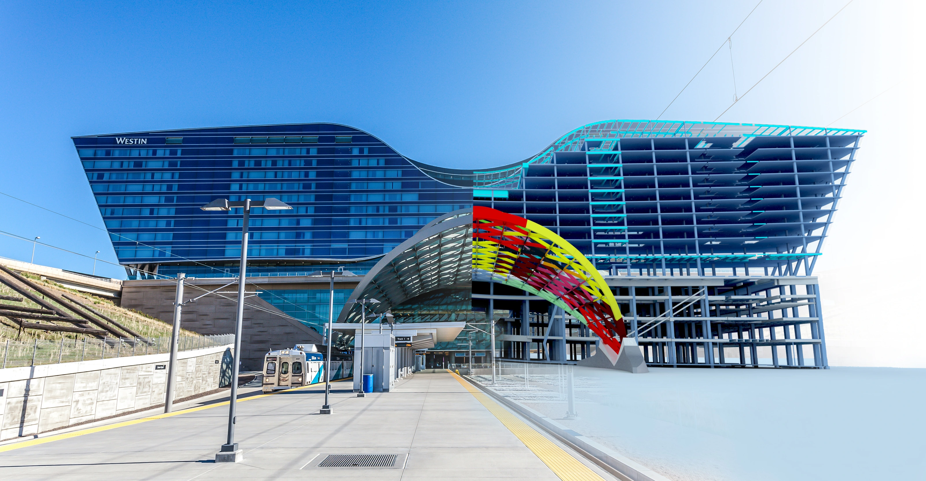
The Denver International Airport project included a new hotel and commuter rail platform comprising more than 2,300 tons of structural steel. At the time, it was the largest project our team had delivered using the design-detailing process.
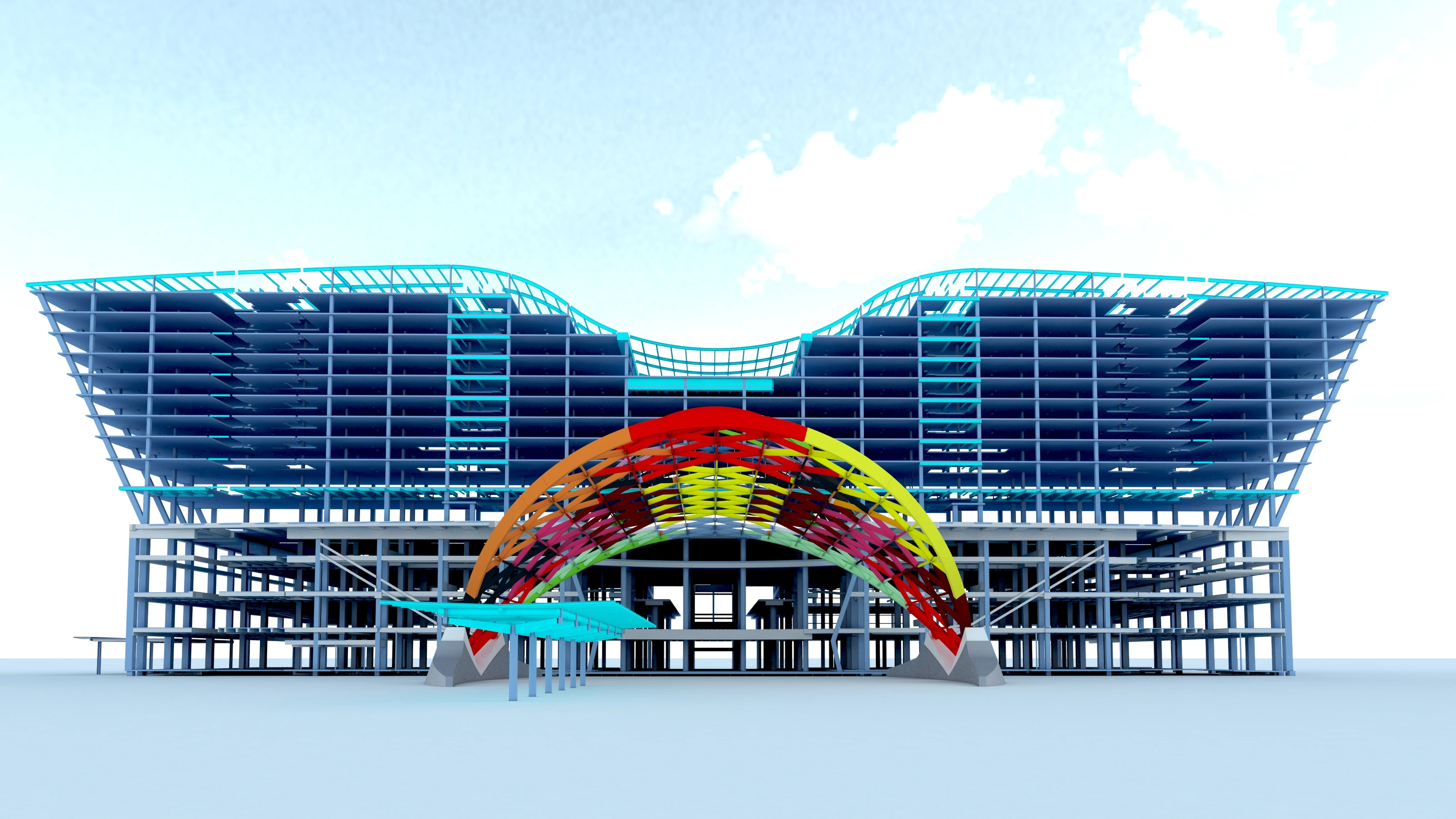
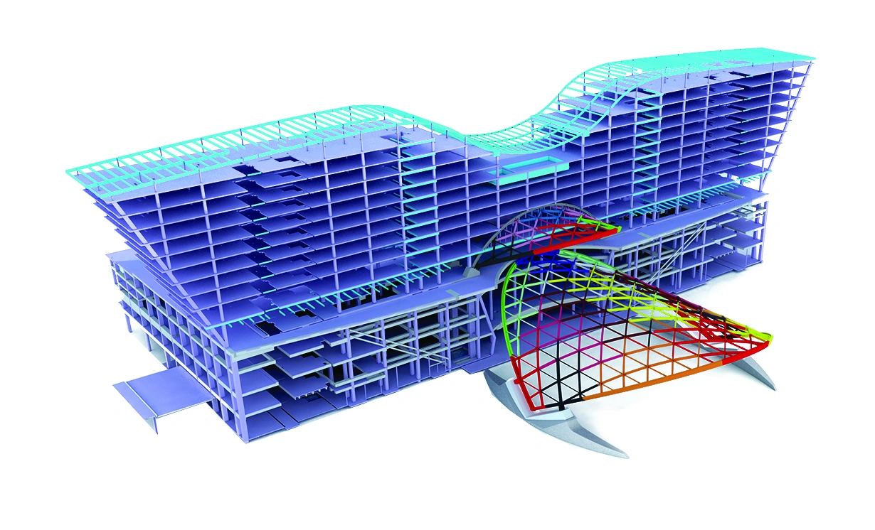
The defining elements of the structure were two exceptionally large and geometrically complex steel canopies. One is a freestanding canopy spanning more than 120 feet above the train platform. The second, larger canopy extends beneath the hotel and is integrated with the arches supporting the building above.
Detailing scope
More than 2,300 tons of structural steel were developed through the collaborative design-detailing process.
A moment-welded diagrid canopy spanned more than 120 feet above the commuter rail platform.
The larger canopy continued beneath the hotel and extended beyond its north and south sides, integrated with the building’s supporting arches.
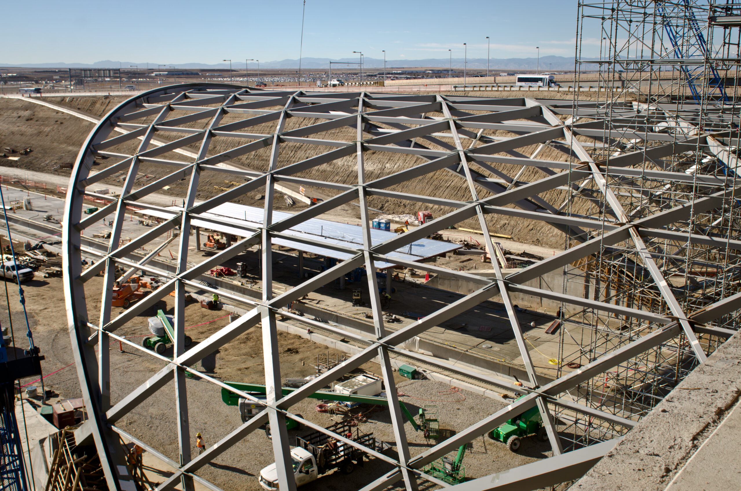
Complete joint penetration welds and multiple internal stiffeners were developed within complex, skewed connection conditions.
Connections were reviewed in the shared 3D model with constructability, welding access and shop sequence in mind.
Model to field
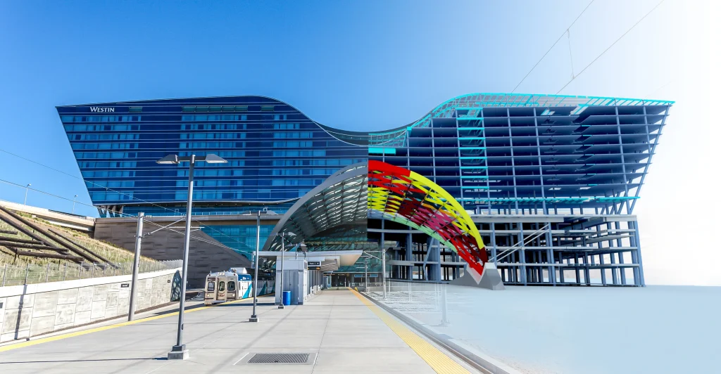 01 / Coordinated model
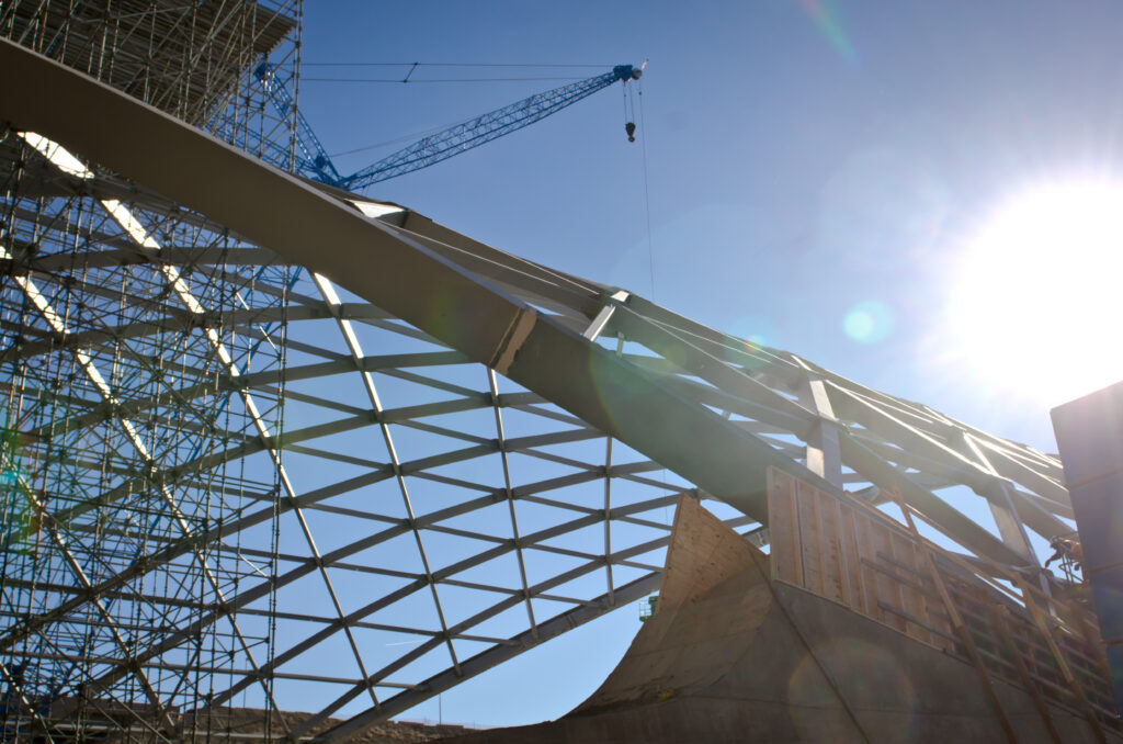 02 / Fabrication & field
Technical complexity
Several internal stiffeners converged inside individual joints at irregular angles, leaving limited space for complete joint penetration welds.
Intersecting structural elements and non-orthogonal connections needed coordinated three-dimensional definition before fabrication release.
The larger canopy had to remain coordinated with the hotel structure and its supporting arches as connection conditions developed.
The design-detailing workflow used the model to review difficult joints with the engineer, shortening successive RFI cycles and maintaining continuity through fabrication.
Our approach
Instead of relying exclusively on the traditional RFI process through the fabricator, the project used a collaborative design-detailing workflow. The 3D model became the primary environment for developing and coordinating complex connections with the engineering team.
Potential conflicts could be identified earlier, while difficult diagrid joints and stiffener arrangements could be reviewed before reaching the shop floor. This reduced the time normally required for successive RFIs and helped maintain continuity between engineering, detailing and fabrication.
Both canopies use moment-welded diagrid systems designed to transfer structural loads across their surfaces and into massive supporting abutments.
The project’s complex geometry required close coordination between the engineering and detailing teams. Working within a shared 3D environment allowed connection conditions, internal stiffeners and intersecting structural elements to be evaluated before fabrication information was released.
This collaborative approach gave the project team greater visibility into difficult conditions and helped resolve constructability challenges directly within the model.
Project animation
Project result
According to the project team, the design-detailing process significantly improved the schedule. The collaborative 3D workflow provided a more direct way to address complex connection conditions than the traditional RFI-based process.
We believe this approach contributed to the project being completed approximately six months ahead of schedule.
“The project was an exceptional success. Having the 3D model and collaboration available with the Tekla team was a great asset to the project. The schedule benefited greatly from having Miro carry the detailing contract.”
Joe Rapp Engineer of Record, S.A. Miro, Inc.