
Elliptical rings and twisting members
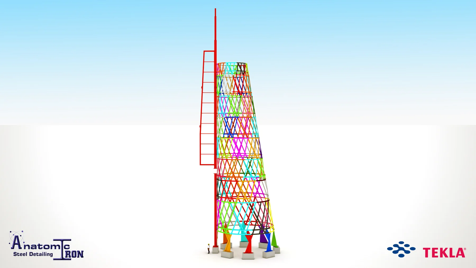
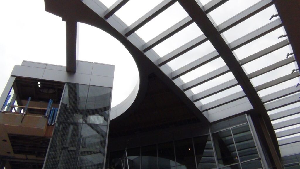
The 70-ton package included nonstandard rolled rings, partial rings and continuous members following the inclined, truncated elliptical cone.
Education
Complex rolled-steel geometry transformed into fabrication-ready information.
Project overview
The Truncated Elliptical Cone formed a specialized portion of the NC State University Talley Student Center Addition and Renovation. Although the package contained approximately 70 tons of structural steel, its geometric complexity required a separate detailing contract and a level of effort more typical of a substantially larger project.
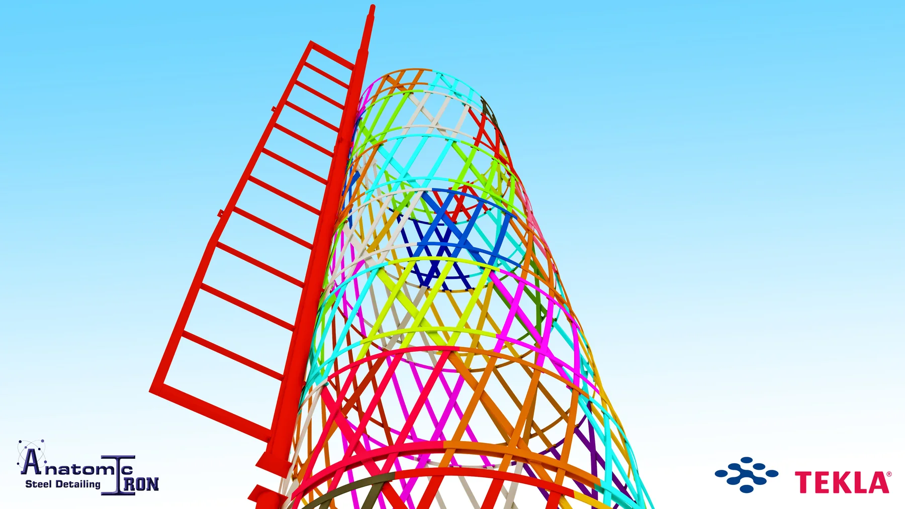
Approximately 90% of the steel within this scope required rolling into nonstandard geometric forms. These included elliptical rings, partial rings, and continuously twisting members following the surface of an inclined, truncated elliptical cone.
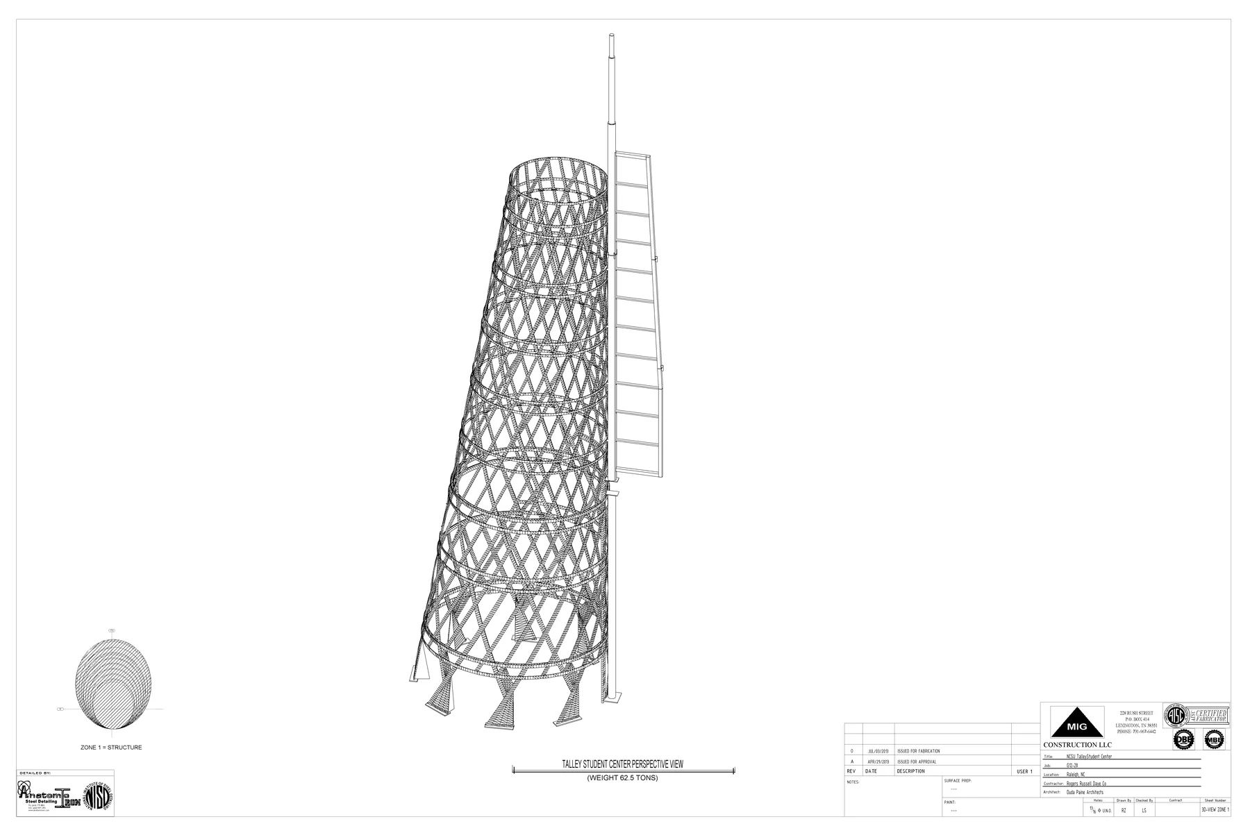
The cone extended approximately 115 feet vertically, with curved members running continuously from the foundation to the uppermost level. Each member had to pass through defined control points positioned along changing elliptical profiles at specific elevations.
Because the structure was both inclined and elliptical, its geometry changed continuously in three dimensions. No two rings or curved sweeps had the same final shape.
Detailing scope
The 70-ton package included nonstandard rolled rings, partial rings and continuous members following the inclined, truncated elliptical cone.
Shapes and control points developed in AutoCAD were transferred into Tekla to define the complete steel assembly in three dimensions.
X-Y-Z tables and CSV coordinate data provided spatial points for forming and checking the unique curved members.
Shop drawings, 3D PDFs and DXF exports communicated geometry that conventional drawings alone could not fully describe.
Model to field
 01 / Coordinated model
 02 / Fabrication & field
Technical complexity
The inclined cone extended approximately 115 feet vertically. Each sweep passed through control points on changing elliptical profiles at different elevations.
Approximately 90% of the steel required rolling. No two rings or curved sweeps had the same final geometry.
The accurate model had to become practical rolling and fabrication information, requiring tailored drawings, coordinate tables and complementary digital exports.
Our approach
Creating the Tekla model was only part of the assignment. The geometry also had to be translated into information that could be understood and used by the rolling facility and fabrication shop.
The team produced multiple digital deliverables, including:
The coordinate tables provided the fabricator with defined spatial points for forming and verifying the complex curved members. This information was particularly important because conventional shop drawing methods alone were not sufficient to fully describe the continuously changing geometry.
The project demonstrated the importance of using Tekla Structures as part of a broader digital detailing workflow. Tekla provided the coordinated structural model and drawing environment, while AutoCAD and model-data exports supported the definition and communication of geometry that could not be efficiently represented using conventional detailing methods alone.
The result was a fabrication-focused information package capable of communicating unique rolled shapes, spatial coordinates, and changing three-dimensional geometry with the precision required by the shop.
Project result
Despite its relatively small tonnage, the Truncated Elliptical Cone demanded extensive geometric development, model verification, and specialized drawing preparation.
By combining accurate 3D modeling, coordinate-based fabrication information, and close coordination with the project team, the detailing process transformed a highly complex architectural form into clearly defined and constructible steel components.